
Measuring Rear-Side Irradiance for Bifacial PV Plants
Introduction
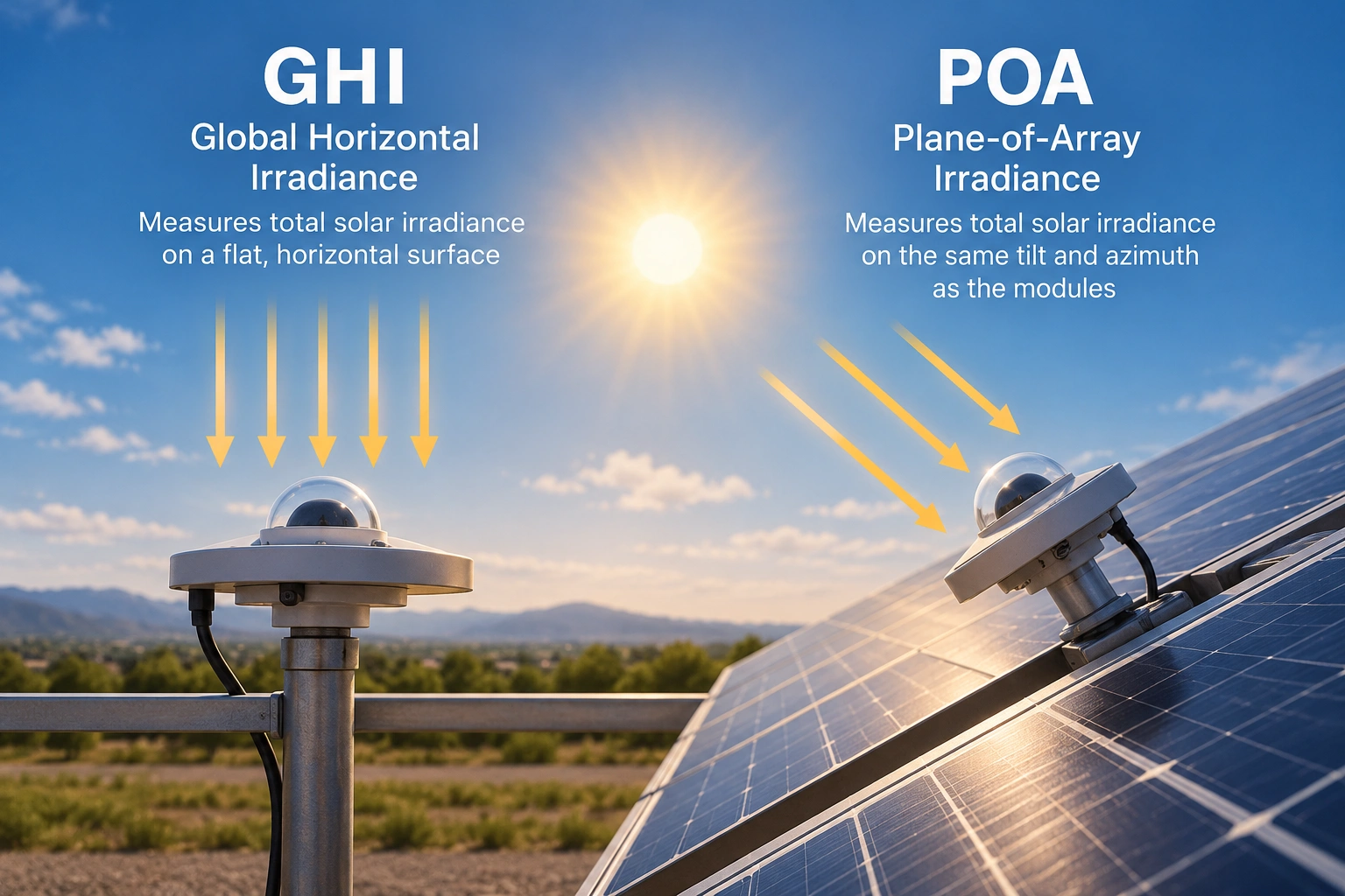
The energy a bifacial PV plant gains from the rear of its modules can only be verified by measuring the light that reaches that side. Front-side plane-of-array (POA) irradiance tells you nothing about it. Without rear-side data, bifacial gain is an assumption in the energy model rather than a number you can check.
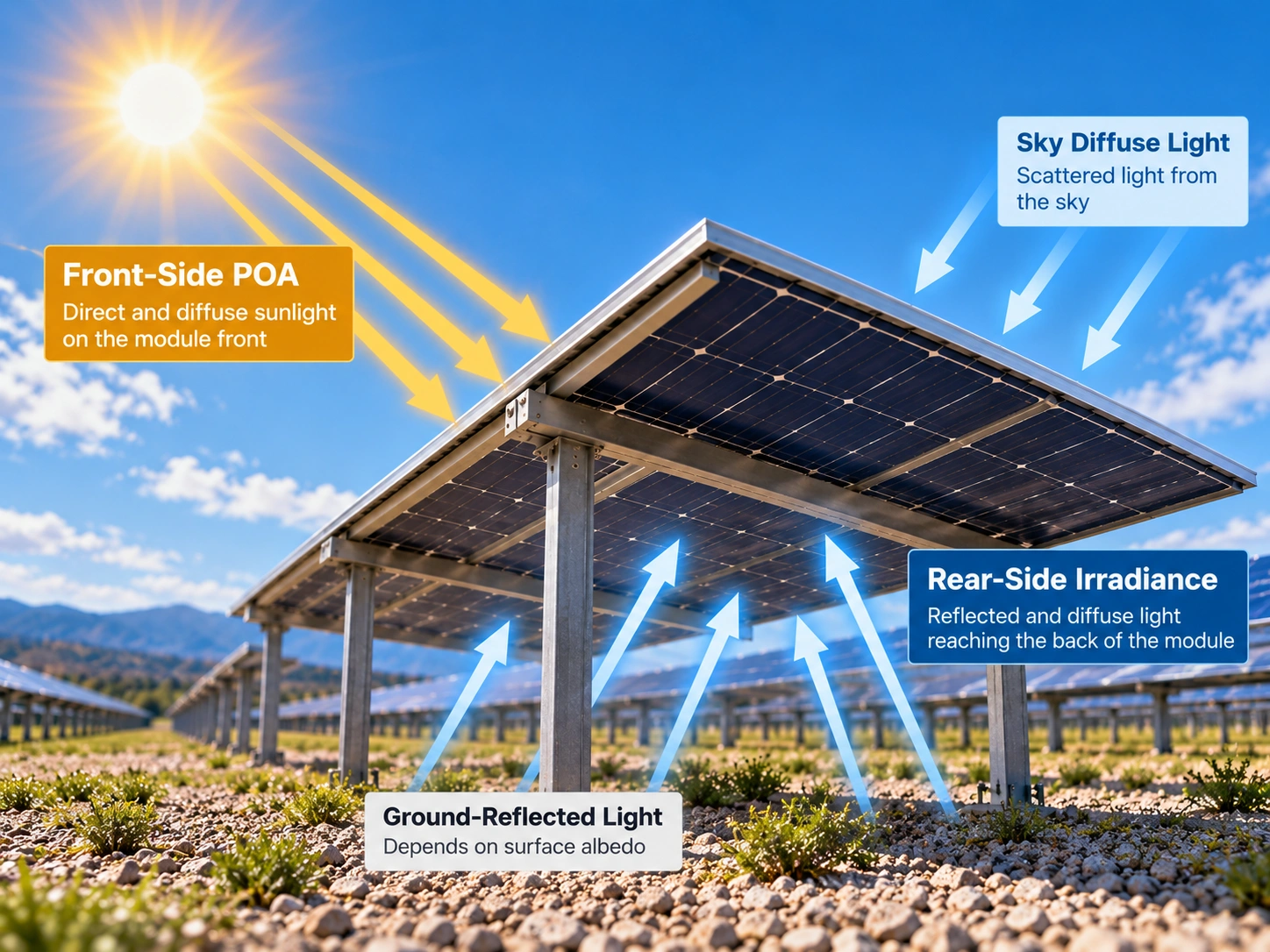
Bifacial modules are now standard on many utility-scale projects, especially on single-axis trackers. The back of each module collects sunlight reflected from the ground and scattered from the sky, adding energy on top of front-side output. How much energy it adds depends on the ground surface, the mounting height, the row spacing, and the weather. All of these vary from site to site and from season to season.
This guide explains where rear-side light comes from, the ways to measure it, what the IEC 61724-1 monitoring standard expects, and how to install and maintain rear-facing sensors so the data holds up.
Where Rear-Side Light Comes From
Most of the light reaching the back of a bifacial module is reflected off the ground. A smaller share is diffuse light arriving directly from the sky, and it becomes more important on high-mounted trackers and on cloudy days.
The ground’s contribution depends on albedo, the fraction of incoming sunlight a surface reflects. Albedo varies widely by surface:
| Ground surface | Typical albedo |
|---|---|
| Fresh snow | 0.75–0.90 |
| White gravel or reflective membrane | 0.40–0.60 |
| Light sand or dry soil | 0.25–0.40 |
| Dry grass | 0.20–0.25 |
| Green vegetation | 0.15–0.25 |
| Dark soil | 0.08–0.15 |
These values are approximate and change over time. Rain darkens soil, vegetation greens up and dies back, and snow comes and goes. A single albedo figure chosen at the design stage rarely matches what the site actually sees month to month.
The array’s geometry matters as much as the ground. Higher mounting and wider row spacing let more reflected light reach the rear surface. Meanwhile, the array shades the ground beneath it, so the area directly under the modules reflects less than open ground between the rows.
Ways to Measure Rear-Side Irradiance
There are two main measurement approaches: measure albedo and model the rear side, or measure the rear plane directly. Many Class A sites do both.
| Approach | What it measures | Strengths | Limitations |
|---|---|---|---|
| Albedometer (up- and down-facing pyranometers, horizontal) | Horizontal albedo and reflected horizontal irradiance | Characterizes the ground; feeds bifacial energy models; comparable across sites | Rear-side irradiance still has to be modeled from it |
| Rear-facing pyranometer in the module plane | In-plane rear-side irradiance | Direct measure of light on the module back; follows tracker rotation | Very sensitive to placement; one point on a non-uniform surface |
| Rear-facing reference cell | In-plane rear-side irradiance, in the module’s spectral response | Responds like the module itself | Spectral and angular behavior differs from pyranometers; harder to compare with front-side data |
| Several rear sensors across the module height | Rear-side irradiance profile | Captures non-uniformity from top to bottom of the row | More hardware, cabling, and maintenance |
An albedometer is the most portable measurement. It describes the ground in a way that doesn’t depend on the array design, so it can be compared with other sites and with design assumptions. It is also the natural input for bifacial energy models.
A rear-facing in-plane sensor answers the more direct question: how much light is actually reaching the back of the modules? It is the closest analogue to front-side POA, and the ratio of rear to front irradiance, often called the bifacial irradiance ratio, is a useful diagnostic over time.
What IEC 61724-1 Says About Bifacial Monitoring
The 2021 edition of IEC 61724-1 added bifacial measurements that the first edition lacked. Its irradiance clause now includes in-plane rear-side irradiance, the rear-side irradiance ratio, and horizontal albedo, alongside the familiar GHI and POA (IEC 61724-1:2021 contents).
A few points matter most for planning a monitoring system:
- Front-side measurements are still required. Bifacial monitoring builds on GHI and POA rather than replacing them. Rear readings can be paired with GHI to give global rear-side irradiance, or with POA to give in-plane rear-side irradiance (EKO Instruments).
- Rear sensors can be a lower class than front sensors. For Class A systems, the up-facing measurements must use Class A pyranometers, while rear-side measurements are permitted at Class C or better. This reflects the lower irradiance levels on the rear and the larger spatial uncertainty.
- Albedo is commonly treated as an optional addition. Many Class A systems include it anyway, because it is the most practical way to validate the energy model.
If your plant’s contract or financing documents cite IEC 61724-1, check which edition they reference, since the 2017 and 2021 monitoring classes are defined differently.
Why Rear-Side Measurement Is Hard
Rear-side irradiance is uneven, so a single sensor sees only one point on a surface that can vary a great deal from edge to edge. That is the core challenge, and it shapes every placement decision.
- Non-uniformity across the row. The bottom edge of a module usually sees more reflected light than the top, and modules at the end of a row see more than those in the middle. On trackers, the pattern shifts as the array rotates.
- Shading by the structure. Torque tubes, rails, junction boxes, and cabling cast shadows on the rear surface. A sensor placed in or near one of these shadows under-reads. One placed in a gap between them over-reads.
- Low signal levels. Rear irradiance is a small fraction of front-side irradiance. Offsets and noise that are negligible on a front sensor become a larger share of a rear reading.
- Changing ground conditions. Mowing, rain, snow, and vehicle traffic alter the albedo under the array, sometimes within a single day.
- Sensor self-shading and view. A downward-facing sensor and its mount block part of the ground they are trying to see, especially when mounted close to the ground.
Because of these effects, rear-side measurements have higher uncertainty than front-side ones. Good installation practice is what keeps that uncertainty manageable.
Installation Best Practices
Place rear sensors where they see the same light as a typical module, not the best or worst spot on the array. The goal is a representative reading.
Rear-facing in-plane sensors
- Mount the sensor in the module plane, facing backward, on the moving structure of a tracker so it rotates with the modules.
- Pick a position in the interior of a row, away from row ends where extra light spills in.
- Keep it clear of torque tube and rail shadows. If possible, place it at a height on the row that represents the module average.
- Where budget allows, use two or more sensors at different heights on the row to capture the top-to-bottom gradient.
- Use an inclinometer to confirm the sensor matches the module tilt, and check it again after tracker commissioning.
Albedometers
- Mount the albedometer level, typically 1.5–2 m above the ground, on a boom that keeps the mast out of the lower sensor’s view.
- Place it over ground that is typical of the array: same vegetation, same soil, same maintenance, and not over roads, gravel pads, or inverter skids.
- Avoid spots where the array itself shades the ground below the sensor for much of the day, unless you specifically want to measure under-array conditions.
On all rear-facing sensors
- Downward-facing domes collect dust from below and are hard to see, so add them explicitly to the cleaning schedule.
- Log vegetation management and snow events alongside the data. They explain many of the step changes you will see in rear readings.
Calibration and Maintenance of Rear-Facing Sensors
Rear-side readings are small, so calibration errors take up a larger share of them. A sensitivity error of a few percent is minor on a 1,000 W/m² front reading. On a rear reading of 100 W/m², the same error can hide the change in bifacial gain you are trying to detect.
A few practices keep rear data trustworthy:
- Calibrate rear sensors on the same schedule as front sensors. The bifacial irradiance ratio only means something if both sensors are traceable to the same reference and drift is controlled on both.
- Calibrate both halves of an albedometer together. Albedo is a ratio of the lower sensor’s reading to the upper one’s, so a mismatch between the two sensors shows up directly as an albedo error.
- Check zero offsets. Thermal offsets are a larger fraction of low rear-side signals, so keep ventilation or heating units, where fitted, in good working order.
- Inspect domes and desiccant regularly. Downward-facing sensors collect dust and splashed soil that are easy to miss from ground level.
At ISO-CAL North America, we calibrate pyranometers and albedometers in our ISO/IEC 17025 accredited laboratory, with results traceable to the World Radiometric Reference. For more on albedo, read Understanding Albedo: Why Accurate Albedometer Calibration Matters and our Albedometer Calibration Guide.
Ready to calibrate your bifacial site’s sensors? Request a quote or start an RMA today.
Frequently Asked Questions
Do I need rear-side sensors if I already measure albedo?
Not necessarily. Albedo plus a good bifacial model is enough for many sites. Direct rear-side measurement is worth adding when bifacial gain is part of a performance guarantee, or when you need to confirm the model against reality.
How many rear-side sensors does a site need?
There is no single answer. Because rear irradiance is uneven, more sensors at different row positions give a more representative average. Many sites place rear sensors at each Class A monitoring station.
Can I estimate bifacial gain from front-side data alone?
Only through modeling, and the result depends heavily on the assumed albedo. Measured albedo or rear-side irradiance cuts that uncertainty considerably.
Why does my rear-side reading jump after mowing or rain?
Both change the ground’s reflectivity. Fresh-cut dry grass and wet dark soil reflect very differently. Logging site maintenance and weather next to the data makes these jumps easy to explain.